HSS Connection Solutions under Seismic Loading – for Braced Frames
HSS Bracings to Gusset Plates
Detailed design examples for bracing-to-gusset plate connections in so-called OCBFs (“Ordinary Concentric Braced Frames” or those designed for a higher seismic force level with very little inelastic deformation), SCBFs (“Special Concentrically Braced Frames” or those designed to a lower force level than OCBFs with detailing provisions to accommodate energy dissipation and inelasticity), EBFs (“Eccentrically Braced Frames” or those where lateral forces are resisted by a combination of flexure, shear and axial forces in the framing members) are given in Part 5 (Braced Frames) of the AISC “Seismic Design Manual”, in accordance with AISC 341-10, AISC 360-10 and ASCE 7. Most of these connection design examples utilize hollow section bracings, in fact exclusively for the SCBF examples, with the bracings all being round HSS. This is indicative of the current preference in the U.S. for round HSS over square/rectangular HSS, for energy-dissipative bracing members.
SCBF connections
With AISC specifications, there are two alternative design approaches available for the connections which accommodate the effects of brace buckling during compression loading cycles (AISC 341-10 Section F2.6c(3); AISC Seismic Manual, 2012):
- F2.6c(3)(a): The connections are strong and rigid enough to force all plastic hinges to occur in the bracing member (i.e. at mid-length and at the ends of the bracing). The connection must then be designed to resist 1.1 times the expected flexural strength of the bracing (RyMp).
- F2.6c(3)(b): Plastic hinges are designed to occur in the gusset plates (causing out-of-plane flexure of the gusset plates) at the ends of the bracings, and at mid-length of the bracing. The connection is thus designed to have sufficient rotation capacity at the frame design story drift. This is usually achieved by leaving a clear distance of at least two times the gusset plate thickness between the line of the bracing end and the intersection of the gusset with the beam or column, for a “fold line”. Another option also sanctioned by AISC is to design the gusset plate for an elliptical rather than a linear yield line (plastic hinge) across the gusset.
Large seismic drifts are associated with repeated yielding and buckling of the braces, which causes issues with rotations in gusseted beam-to-column connections. Two methods are provided (AISC 341-10 Section F2.6b; AISC Seismic Manual, 2012) for accommodating these demands:
- F2.6b(a): The connection may be detailed as a simple connection, providing a minimum rotation capacity (0.025 rad. is specified) so that the beam and column are not constrained to rotate together as the frame deforms.
- F2.6b(b): Rotational capacity may be provided by flexural yielding of either the beam or the column. These members must have sufficient rotational ductility to maintain their function as braced-frame members when subjected to inelastic rotation. An upper bound for the moment demand is taken as the lesser of:
(i.) 1.1 times the beam expected flexural strength (RyMp), and
(ii) 1.1 times the sum of the expected column flexural strengths above and below the connection (ΣZFyRy).
This moment is then used in connection design in conjunction with the bracing forces corresponding to the bracing expected strength.
Fabricated bracing-to-gusset connections in SCBFs frequently require steel reinforcement, especially if some of the bracing cross-sectional area is removed at the connection resulting in a net area less than the gross area, as capacity design dictates that large tension forces must be resisted (AgRyFy). AISC 341-10 in fact mandates that bracings with holes or slots be reinforced such that the effective net area exceeds the gross area.
Proprietary Connections to Gusset Plates
Designing SCBF connections can be time-consuming and requires considerable expertise. Furthermore, the resulting fabricated connection can be expensive and, if architecturally exposed, may not be aesthetic. This has led to the development of “pre-engineered” proprietary solutions in cast steel, such as shown in Fig. 1, where the energy-dissipative bracing system is designed to produce hinging at mid-length of the bracing and in the gusset plates at each end, with the cast connector remaining elastic. Steel castings have experienced a renaissance in steel construction recently and they can be produced to meet the extreme demands of high seismic applications, with adequate strength, ductility, toughness and weldability. Casting also provides 3D geometric freedom which can result in aesthetically appealing, as well as practical, steel connections for tubes (Fig. 2).
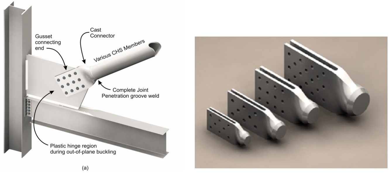
Fig. 1: Cast steel “High Strength Connectors”™ by Cast Connex®, for round HSS bracings in SCBFs
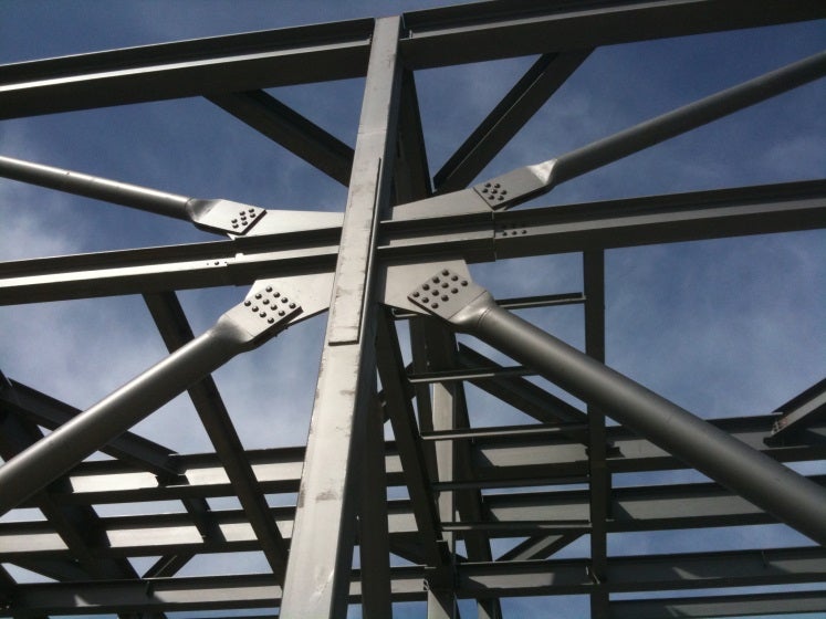
Fig. 2: Cast Connex® “High Strength Connectors”™ in a Gallo Winery building in a high seismic zone (California)
The above castings have received rigorous laboratory testing and verification under approved seismic loading protocols, sufficient for a range of “off-the-shelf” products to be marketed (www.castconnex.com). These castings come in a range of sizes (Fig. 1) to suit CHS of various external diameters. Since the tapered nose of the casting is inserted into the CHS bracing, a range of tube wall thicknesses is accommodated by permitting the CHS to ride up the tapered nose by different amounts. The demand-critical complete joint penetration (CJP) groove weld can be completed and inspected in the fabrication shop, allowing for the connection to be completed by site bolting. A substantially more compact field-bolted connection is achieved than would otherwise be possible with typical bolted connections using splice plates.
Since AISC 358-10 does not prequalify connections for braced frames, a comparable route for qualification of custom seismic products – which does entail proof testing – is approval by ICC Evaluation Services (a subsidiary of the International Code Council) in California. Approval by that body, which will mean review by SEAOC (Structural Engineers Association of California) too, is necessary for public buildings in California. This ICC–ES approval route was thus followed by Cast Connex® for the “High Strength Connector” braced frame product in North America. Relative to self-designed connections, proprietary seismic connections typically offer improved performance, additional quality assurance, technical support by the company staff, and sometimes savings in cost and construction time (AISC “Modern Steel Construction”, October 2011).