
Designing Smarter HSS Truss Connections: The Answer is In the Joints

Every structural engineer knows the feeling. You finish a truss design that hits the lightest possible weight and send it to the fabricator, only for the quote to come back higher than you expected. The culprit rarely lives in the member tonnage, however. It lives in the joints. The devil is truly in the details.
Hollow structural section (HSS) truss connections drive both the performance and the price of the section. The way you proportion member sizes and configure the panel points determines how forces flow, which limit states control your design, and how many labor hours the fabricator spends in the fabrication shop. Master the joints, and you can optimize the entire truss. Below, we will walk through the concepts that help you design HSS connections with confidence, from nomenclature to multi-planar geometry.
HSS Truss Connection Types and Nomenclature
Truss connections occur at the panel points, or joints, of a planar truss. Before you select any sizes or determine joint configurations, you need a shared language. AISC notation, found in the “Symbols” section of the Steel Construction Manual, defines the chord with capital letters (D, B, H, t) and the branch with the subscript “b” (Db, Bb, Hb, tb). The angle θ describes the branch orientation relative to the chord, “g” marks the gap between branches, and overlap follows the formula (lov/lp) × 100% = Overlap. Eccentricity (+e or −e) captures how far the working points sit from the chord centerline.
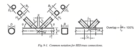
Become comfortable with these symbols. They reappear in every limit state equation in Chapter K and other design guides you may reach for. (AISC Design Guide #24, 2nd Edition)
Three Ways to Analyze a Planar Truss
Engineers typically analyze the joints as pinned, then design the members to carry tension and compression. This pinned assumption was introduced so that trusses, which are statically indeterminate, could be analyzed by hand.
Now that we do our analyses with a computer, you have three options when analyzing planar welded HSS trusses:
- Pin-jointed analysis—model all members connected to a pinned joint.
- Pinned web members with continuous chords—model branch members as pinned to an extremely stiff member, which can be used to model the nodal eccentricity.
- Rigid frame analysis—model all members connected at a fixed joint.
Methods 1 and 2 will result in axial forces in the branch members. AISC 360, Chapter K is based on web members with axial forces only. Method 3 will result in axial and bending (moments) forces in the member. Method 2 is the recommended method. Refer to AISC Design Guide 24 (2nd edition), Chapter 9, Section 9.4 for a more detailed discussion on this topic as well as recommendations for magnification factors to consider when looking at serviceability (deflections) of trusses.
Recognizing the Failure Modes
Understanding how forces flow through joints and potential HSS failure modes is the key to good joint behavior and good connection design. Square and rectangular HSS connections can experience all the following failure modes, while round HSS typically are controlled by only the first two:
- Plastification of the chord face—the most common mode in T, Y, X, and gap K/N joints, especially when the branch to chord width ratio b falls below 0.85.
- Chord punching shear—based on shear yielding of chord material. Rectangular HSS use an effective width because stress concentrates near the chord edges, while round HSS distributes stress evenly around the footprint.
- Chord sidewall buckling or yielding—a potential failure mode for rectangular sections with b close to 1.0, the so-called “matched” connections.
- Brace local buckling—the most common compression failure in overlapped rectangular connections; you avoid it by meeting joint parameter limits.
- Chord shear failure—occurs in gapped K-joints when the gap exceeds limits or when the chord carries a low depth-to-width (H/B) ratio.
- Chord local buckling—occurs with rectangular HSS in overlapped K-joints due to shear lag when high axial force is carried in the connecting face of the chord; following wall slenderness limits will prevent this.
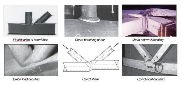
Understanding each failure mode and how they occur can help you optimize your connection design.
For a deeper understanding of these limit states, refer to AISC Design Guide 24, Section 9.2.2.
Knowing Your Joint Types
Joint types may look like they are driven by their geometry (a K looks like a K). However, classification of joints depends on how the joint transfers force, not on how it looks. When a branch transfers part of its load one way and part another way, you check each portion through interaction. The main planar joint types include:
- T- or Y-joints, where a single branch meets the chord.
- Gap K-joints (and N-joints), where two branches frame in with a gap between them.
- X-joints (Cross), where forces pass through the chord to an opposing branch, or an external load is applied at a joint.
- Overlap K-joints, where one branch overlaps the other.
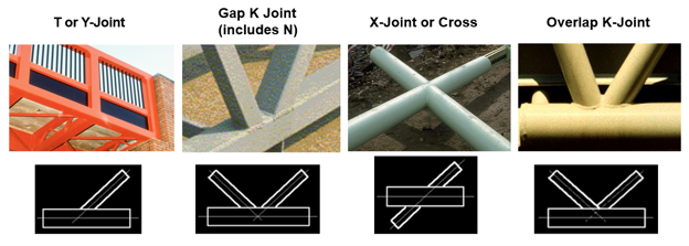
Each joint type serves a different function for HSS truss connection load transference.
Refer to AISC Design Guide 24, Section 9.3 for additional insights into joint classification.
How Member Size Selection Impacts Joint Strength
Proper selection of member sizes can lead to successful joint design. Here are six factors to consider for increasing performance of the joints:
- Chord wall slenderness: Members with lower D/t or B/t raise joint capacity. This leads to stocky chord members, which is counter to traditional thinking. Usually, one would consider a larger thin-walled chord to improve global stability of the chord. However, a smaller member with thicker walls leads to a stronger and stiffer joint, as well as a more efficient truss. Target 15 < D/t < 30 for round chords and 15 < B/t < 25 for square chords.
- Branch wall slenderness: Use thinner branch walls relative to the chord walls and use a branch member with a high D/t or B/t ratio. Keep the ratio of the branch wall to the chord wall as low as possible. Keeping the branch wall thinner than the chord wall improves weld design by avoiding welding “thick to thin”.
- Branch-to-chord width ratio: Keep the ratio of the branch width to the chord width high to lift joint capacity. This, along with high branch wall slenderness ratios, will add to joint strength and stiffness. For practical reasons, it is best to hold the width of the branch member to not exceed the workable flat of the rectangular chord. This will allow the placement of fillet welds around the branch member. If a “matched” connection (where the branch and the chord are the same width) is used, then a flare bevel weld will be needed. This will likely increase fabrication costs.
- Bracing angle: Lowering the angle of the branch member relative to the chord member will increase joint capacity. However, lowering the bracing angle below 30 degrees will make welding of the branch heel more difficult. It is best to respect this practical limit for improved fabrication.
- Chord force to yield ratio: Keep the actual-to-yield force ratio low in the compression chord; using those stocky sections discussed above will deliver this.
- Overlap percentage: Overlapped joints will provide more strength and stiffness compared to gapped joints. Partial overlaps are stronger than 100% overlaps, but the overlap should be at least a minimum of 25% for two practical reasons:
-
- Load transfer: Too little overlap can reduce the effective load-transfer area, which may weaken the joint.
-
- Joint performance: Sufficient overlap can improve joint stability and, depending on the design, may reduce the risk of premature failure.
Welding Best Practices
Improving welding practice leads to more efficient fabrication. Specify fillet welds for tubular joints whenever possible. Most of the time, when you size the members properly, you can use fillet welds to carry the forces in the joints. It is best to avoid costly complete joint penetration (CJP) welds entirely. CJP welds can be difficult to fit up and weld.
One important caution: do not apply the directional strength increase for fillet welds to HSS. Refer to Section J2.5 of AISC 360 (Specification for Structural Steel Buildings) and the associated Commentary for more information.
There are two philosophies when it comes weld design:
- Approach 1 develops the full yield strength of the branch, giving a conservative upper-bound weld size. This may be appropriate when plastic stress redistribution is required in the connection. The same effective weld size is used on all sides, except possibly at the “hidden toe” of partially overlapped connections. Refer to AISC Design Guide 24, Section 3.5 for more on this topic.
- Approach 2 proportions the weld size to resist the actual member forces. This is appropriate for the typical case where the branch forces are low relative to the strength of the branch member. This also uses the same effective weld size on all sides of the branch member but requires that effective weld lengths be used.
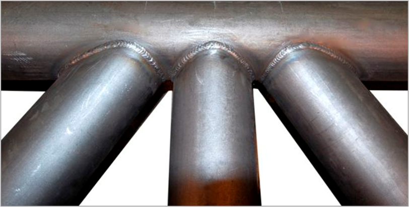
Fillet welds are generally the optimal weld choice for HSS truss connections.
Optimizing Fabrication Cost
Minimum weight does not equal minimum cost. To control fabrication dollars, follow these guiding principles:
- Avoid bracing angles less than 30 degrees. This is a practical limit related to fit up and fabrication of joints.
- Use fillet welds. Fillet welds are more cost effective and easier to achieve.
- Minimize the number of connections. A Warren truss has the minimum number of members and therefore will have the fewest joints.
- It is best to size the members of the truss to increase joint strength, rather than optimize the truss for least weight. Matched connections (where the branch and the chord are the same width) can be more costly to fabricate since they require a flare bevel weld at the corner radius. Matched connections are preferred.
When attempting to optimize fabrication costs, remember the type of joint will impact cost. So, think about your joints when you are choosing your members instead of after. Gapped K connections are the simplest and easiest to fit up and fabricate. For most typical trusses, this is the best solution. Other joint types have higher strength and stiffness; however, this comes at a higher fabrication cost.
From lowest to highest cost, the hierarchy runs:
Gap Joints
100% Overlap
Gap Joints
Partial Overlap
100% Overlap
Partial Overlap
Truss Splices and the Shuriken® Advantage
Splices may be necessary to aid the transportation and erection of long-span trusses. Bolted splices are faster, safer, and easier, and are thus preferred over field welding.
The Shuriken® Structural Nut Keeper offers an option for one-sided connections, using standard A325 or A490 bolts. Shuriken is designed to handle the installation torque required to pre-tension the bolts, and therefore supports slip-critical connections. Compared to welding, Shuriken offers faster, safer and more cost-effective erection.
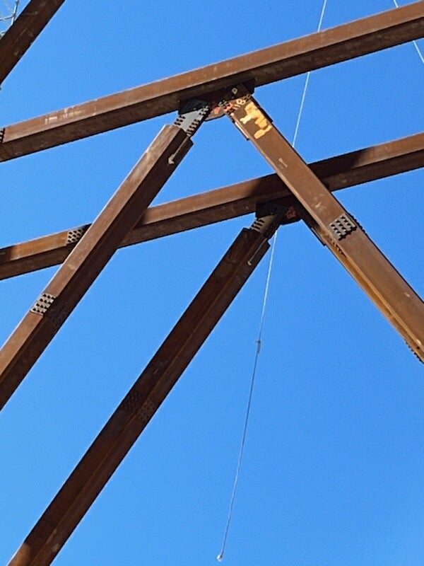
Using Shuriken can enable project teams to field-bolt HSS, simultaneously increasing efficiency and decreasing costs.
Key Takeaways
Efficient HSS truss design depends on the joints. Keep these principles in mind during early design:
- Think about member sizes and their impact on the joint design during the initial design phase.
- Choose stocky chords with low D/t or B/t, which can also trim surface area and reduce painting costs.
- Specify branches with larger diameter and thinner walls and avoid welding thick to thin.
- Consider joint type and the flow of forces.
- Favor gapped K-connections and fillet welds in all four sides, and steer clear of matched connections unless absolutely necessary.
- Always consider the impacts on fabrication when making design decisions.
- Keep bracing angles practical.
- Fillet welds are typically the most efficient choice.
- Use a minimum overlap of 25% for overlapped connections.
Connection design defines the success of your truss far more than tonnage ever will. When you treat the joint as the starting point rather than an afterthought, you deliver truss designs that perform well, fabricate efficiently, and are easier on your budget.
For deeper guidance, AISC Chapter K, Design Guide 24, the CIDECT guides, and the Atlas Tube Engineering Experts team can help. If you’re designing a new HSS truss connection from scratch, try the complimentary HSS Connections Hub™ and its comprehensive Connection Calculators, which cover 16 different HSS truss connection types.
Brad Fletcher, Senior Structural Engineer at Atlas Tube, holds the S.E. license—structural engineering’s most advanced credential. With 30+ years of practice, he has served as an HSS industry liaison since 2011.