The Atlas Tube HSS Connections Hub™ is a resource designed to streamline connection design for structural engineers and connection designers. It can also help reduce overall fabrication costs. This user-friendly platform features three resources to simplify HSS: a typical detail library, connection calculators, and support from our structural engineering team. Today, we’ll take a tour through the core features and demonstrate how the HSS Connections Hub can make HSS design more efficient.
First, make sure to create a free Connections Hub account.
Now that you’re logged in, let’s go through an example of how to design an HSS connection in the Hub.
First, create a new project and fill out any pertinent reference details. When you’re ready to start a new connection, click Add New Calculation and choose from the connection types available. The current library of connection types include:
- WF to HSS Shear Connections
- Single-Plate
- WT
- Single Angle
- Double Angle
- Through-Plate
- Unstiffened Seated
- Round HSS Through-Plate
- Round HSS Single-Plate
- HSS to HSS Shear Connections
- Coped Beam
- Exterior Plates
- Single Plate
- Through Bolt & Coped Beam
- Field-Welded
- Field-Welded Exterior Plates
- Round HSS Single-Plate
- Unstiffened Seated
- Field-Welded Double Shear Tab
- HSS to WF Shear Connections
- Bolted Double-Angle
- WF to HSS Moment Connections
- Flange Plate
- WT
- Wrap-Around
- Diaphragm Plate
- Round HSS Wrap-Around
- Round HSS Flange PL
- HSS to HSS Moment Connections
- Stiffened Seat
- Stiffened Seat (WT)
- Fin Plate
- Field-Welded
- HSS Steel Base Plate
- Bracing to Beam Field-Welded
- Round HSS Fin Plate
- HSS to WF Moment Connections
- Stiffened Seat
- Fin Plate
- HSS to HSS Splice Connections
- Single-Shear
- Double-Shear
- Single-Shear Exterior
- End Plate
- Single-Shear Field-Welded External
- PJP Weld
- Round HSS PJP Splice
- HSS Truss Connections
- Y-Connection
- K-Connection with Round HSS
- K-Connection with Rectangle HSS
- Overlapped K-Connection with Rectangle HSS
- Overlapped K-Connection with Round HSS
- Y-Connection with Round HSS
- X-Connection with Rectangle HSS
- Overlapped KT-Connection with Square HSS
- Vierendeel Connection In-Plane with Square HSS
- T-Connection Moment Out-of-Plane with Rectangle HSS
- Chevron Bracing
- Symmetrical Bolted Chevron Bracing
- Two-Sided Welded Chevron Bracing
- Symmetrical Welded Chevron Bracing
We are adding new connections and feature updates every two weeks, so watch your email and in-app messages for specific alerts.
Once a connection type is chosen, use the Key Properties column to select the intended member sizes and loadings to start designing a connection.
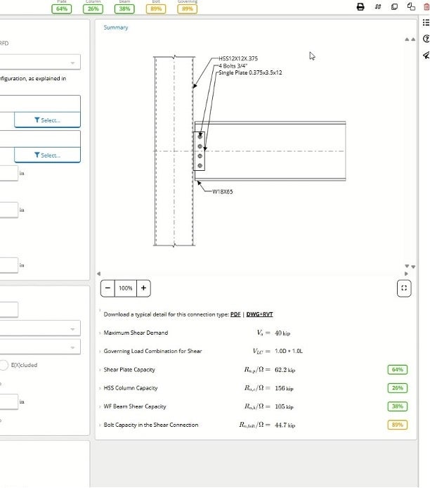
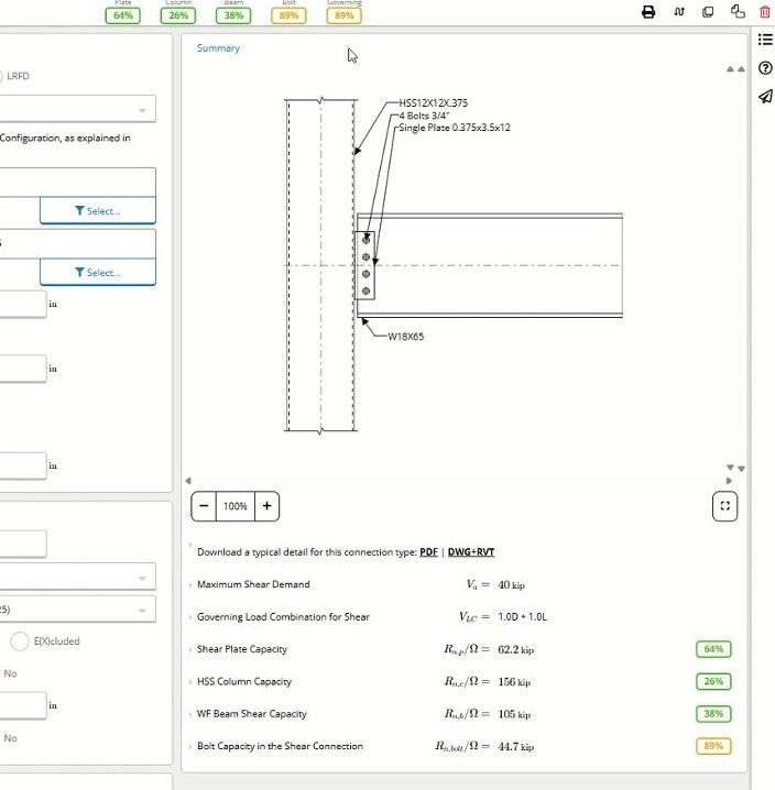
In this guide, we are calculating a WF-HSS Shear Single Plate connection with a W18x65 beam and an HSS 12×12 column.
Use the fields in Key Properties to enter calculation parameters such as the plate thicknesses, weld sizes, edge distances, bolt properties, and loading. To the right of Key Properties is the Summary section, where you’ll find a live diagram of the connection that will respond to calculation changes.
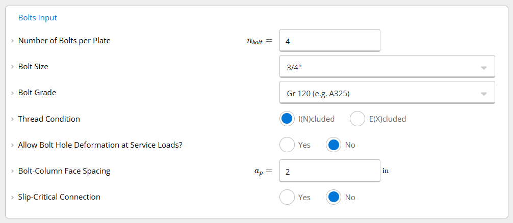
For example, if we were to navigate to the Bolt Inputs section and change the number of bolts to 5 instead of 4, the graphic would respond accordingly.
For this example, we’ll stick with 4 bolts.
The Bolt Inputs section also allows for the changing of bolt size, grade, exclusion or inclusion of the threads in the sheer plane, and the ability to choose slip-critical if necessary.
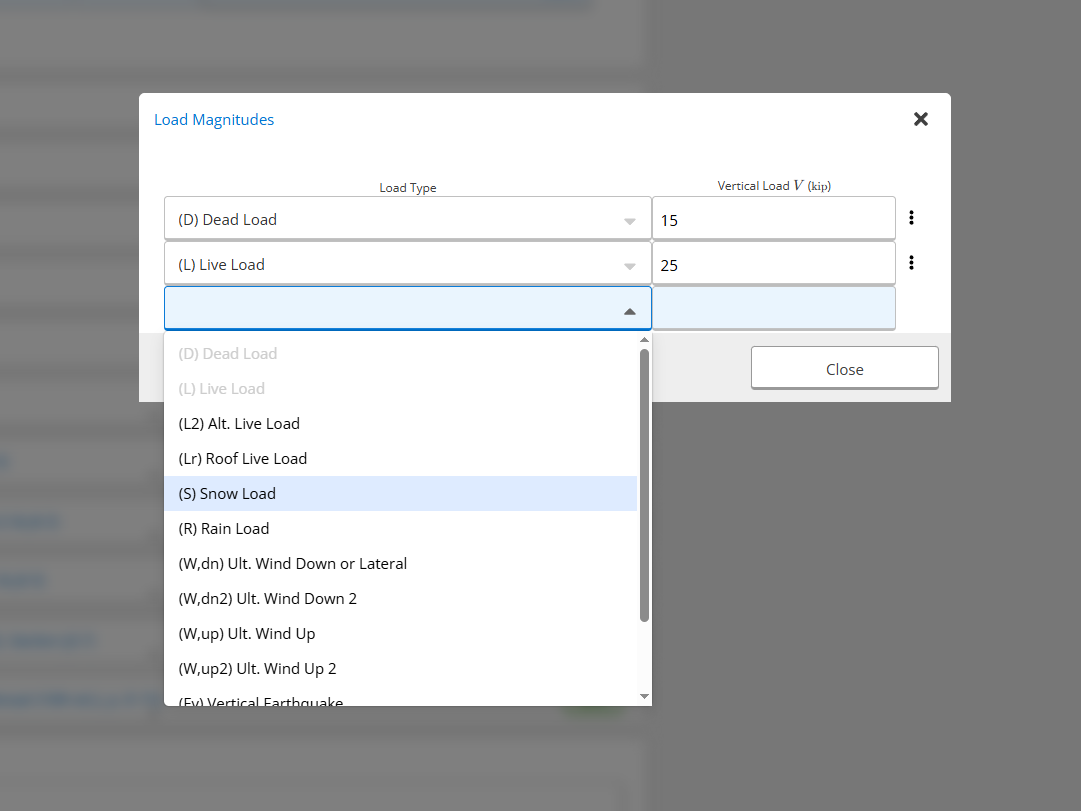
Further down the page in the Applied Loads section, we can add or remove loads and also edit the connection load magnitudes. For this example, we’ve already put in some simple dead and live loads, but the calculator can also accommodate snow loads, seismic loads, and more.
Below the Load Magnitudes section, there are more sections with other load parameters such as basic geometric properties of the column and beam to edge distances can be adjusted. Even further down in the calculator, there are more sections that can be expanded to see the equations going into the connection.
The Hub is designed for full transparency. The high detail level of each dropdown menu ensures that engineers receive an answer for their connection and also have the necessary information and code references to understand each calculation line’s process.
For example, if you expand the Shear Plate Capacity section to examine the sheer yielding of the sheer plate in our current calculation, you can see the utilization percentage at the bottom as well as an explanation of what the limit state is checking with a code reference.
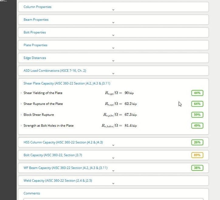
In the Summary section, the calculator also checks HSS column capacity, bolt capacity, the capacity of the web of the beam, and minimum weld size underneath the graphic and at the top of the window in a color-coded set of utilization numbers. Any number above 100% means that changes are required to make the connection meet code.
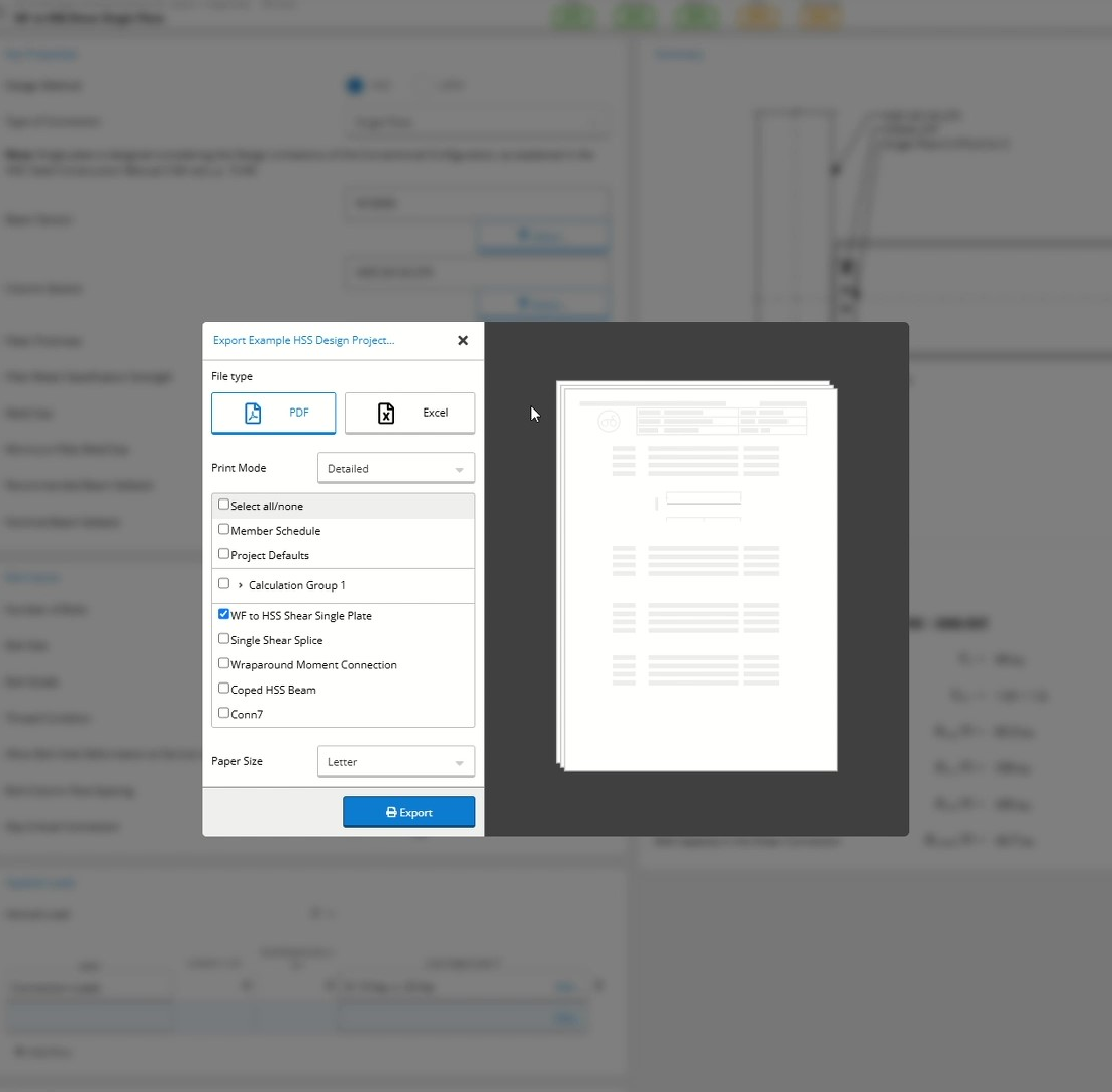
Once the calculation is complete, we can produce a report showing the results of the calculation.
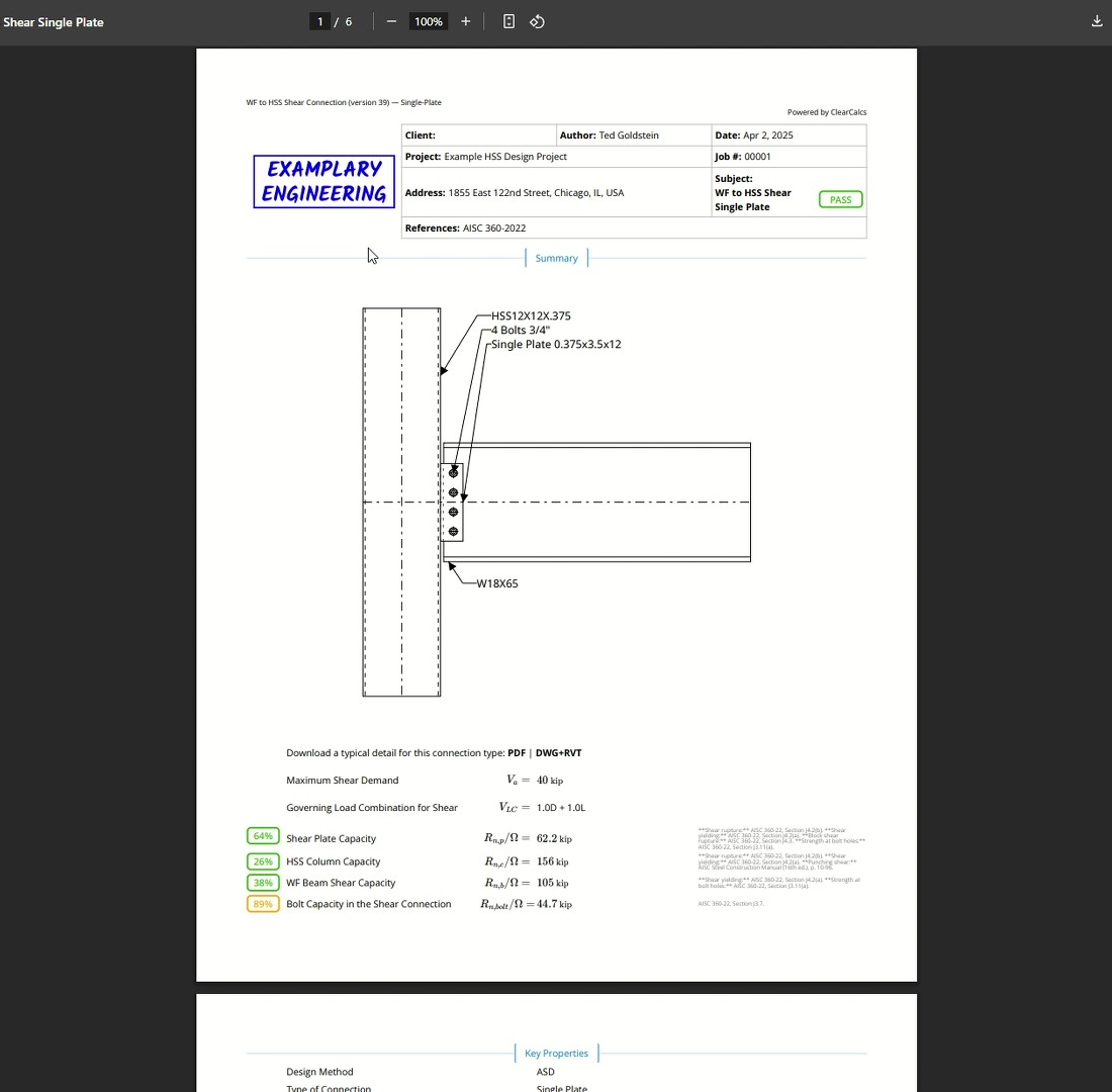
By clicking Export in the top right of the screen above the Summary, a PDF report can be produced in either a summary or a fully detailed version. Here, we have opted for the fully detailed version, which includes every single line of calculations and code references. Users are also able to insert their company’s logo at the top of the report.
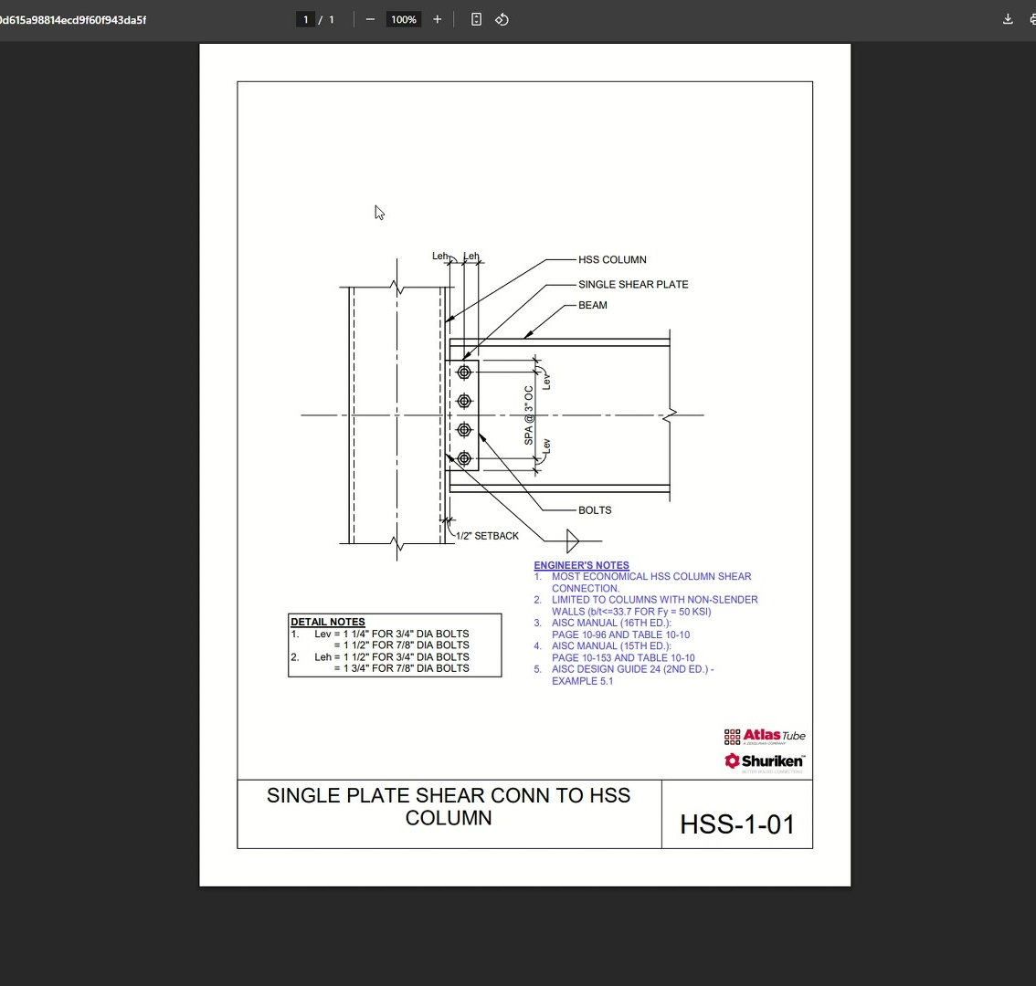
You can also use the Summary section to quickly export typical connection details available in DWG, Revit, and PDF formats. In this example, we clicked PDF underneath the graphic and accessed an engineering-type drawing that can be placed directly onto contract documents with minor changes to account for project-specific conditions. Note that the downloadable detail does not reflect the actual calculation done by the calculator. The Hub currently features 53 downloadable details, including 11 new splice connection details and 9 unique brace connection details.

After that, we’re done with our connection and have a neat, detailed report to share with your project team.
The combination of connection calculators and typical details in the Hub makes it much easier for engineers to produce efficient designs without reinventing the wheel or starting from scratch.